
Raytron at SNEC PV+ 2026: Composite PV Ribbon
June 3-5, 2026 · National Exhibition and Convention Center (Shanghai), Shanghai, China · Hall 2.2, Booth B130
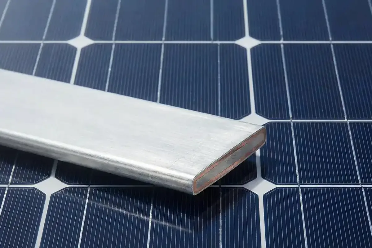
Raytron presented copper–aluminum composite ribbon concepts for multi-busbar and back-contact modules. Follow-up work compares resistance, soldering, line performance and module reliability with the current ribbon.
Date
June 3-5, 2026
Venue
National Exhibition and Convention Center (Shanghai), Shanghai, China
Booth
Hall 2.2, Booth B130
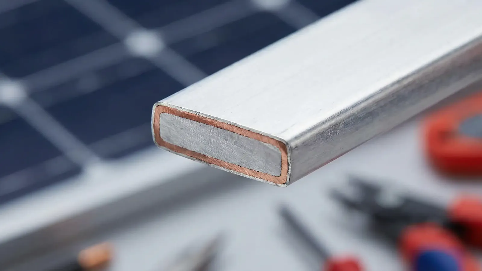
Raytron New Energy (Zhejiang) Co., Ltd. exhibited at SNEC PV+ 2026 from June 3 to 5 at the National Exhibition and Convention Center in Shanghai. At Hall 2.2, Booth B130, the company presented Cu-Al composite photovoltaic ribbon concepts for multi-slice, multi-busbar and back-contact module platforms.
Conductor and cell design
The ribbon combines a copper-aluminum conductor with a solderable surface selected for the joining process. State the core, copper fraction basis, round diameter or flat width/thickness, coating and mechanical condition.
Cell metallization, contact layout and stringer conditions determine the candidate geometry and coating. Compare shading and resistance together, then check coating wetting, peel behavior and cell damage under the actual process.
What to compare in the trial
- Geometry: thickness, width or diameter, tolerance, roundness, flatness, camber and winding quality;
- Electrical performance: resistance per unit length, conductivity, series loss, module power impact and hot-spot risk;
- Soldering: solder-layer thickness and uniformity, wetting, stringing temperature, flux, speed, peel force and joint consistency;
- Mechanical compatibility: tensile properties, elongation, yield behavior, repeated bending, post-solder stress, cell bow and breakage risk;
- Equipment compatibility: payoff, tension, straightening, soldering head, vision system, cycle time and unplanned stops;
- Reliability: thermal cycling, damp heat, mechanical load, potential-induced degradation, corrosion and long-term power stability;
- Economics: material savings, process investment, yield change and qualification cost per meter, cell, module and gigawatt.
Inputs for a sample review
- Cell technology: TOPCon, HJT, BC or another platform; cell size, slicing strategy and busbar layout;
- Current ribbon type, dimensions, tolerances, temper, solder alloy and coating thickness;
- Target resistance per unit length, module power or copper-reduction/cost target per GW;
- Stringer model, line speed, soldering temperature, flux, tension and peel-force standard;
- Module layout, series-parallel configuration, operating current and reliability requirements;
- Sample quantity, validation timing and expected annual volume or production capacity.
Check the production settings
Evaluate payoff tension, guides, soldering temperature/profile, head configuration, speed, vision settings and quality criteria on the intended line. Record required adjustments and the resulting feeding, yield and joint data before approving the changed process.
Booth and Exhibits
Frequently asked questions
Which module platforms can be evaluated?
Will composite PV ribbon always reduce module cost?
Does the customer need a new stringer?
How can samples be requested?
Submit a Specification to Start the Review
Share your basics and current specification highlights. Raytron engineering will run an initial application, electrical, thermal, mechanical, processing, joining and environmental review.
Related Products and Applications
Related Events
Final performance and delivery are subject to mutually confirmed drawings, technical agreements, test methods and lot inspection data.