
Engineering application guide
Inverter Magnetic Component Windings
An inverter winding must meet the losses and temperature rise permitted by its switching duty. Copper-clad aluminum (CCA) foil and flat wire are candidates to evaluate within the actual inductor or magnetic-component assembly.
Discuss the assembly requirementsOn this page
Locate the magnetic component winding
- 1Inductor or transformer winding
- 2Insulation between turns/layers
- 3Terminations and thermal path
Foil and flat wire occupy different winding envelopes. Select the geometry around the actual magnetic component and its waveform.
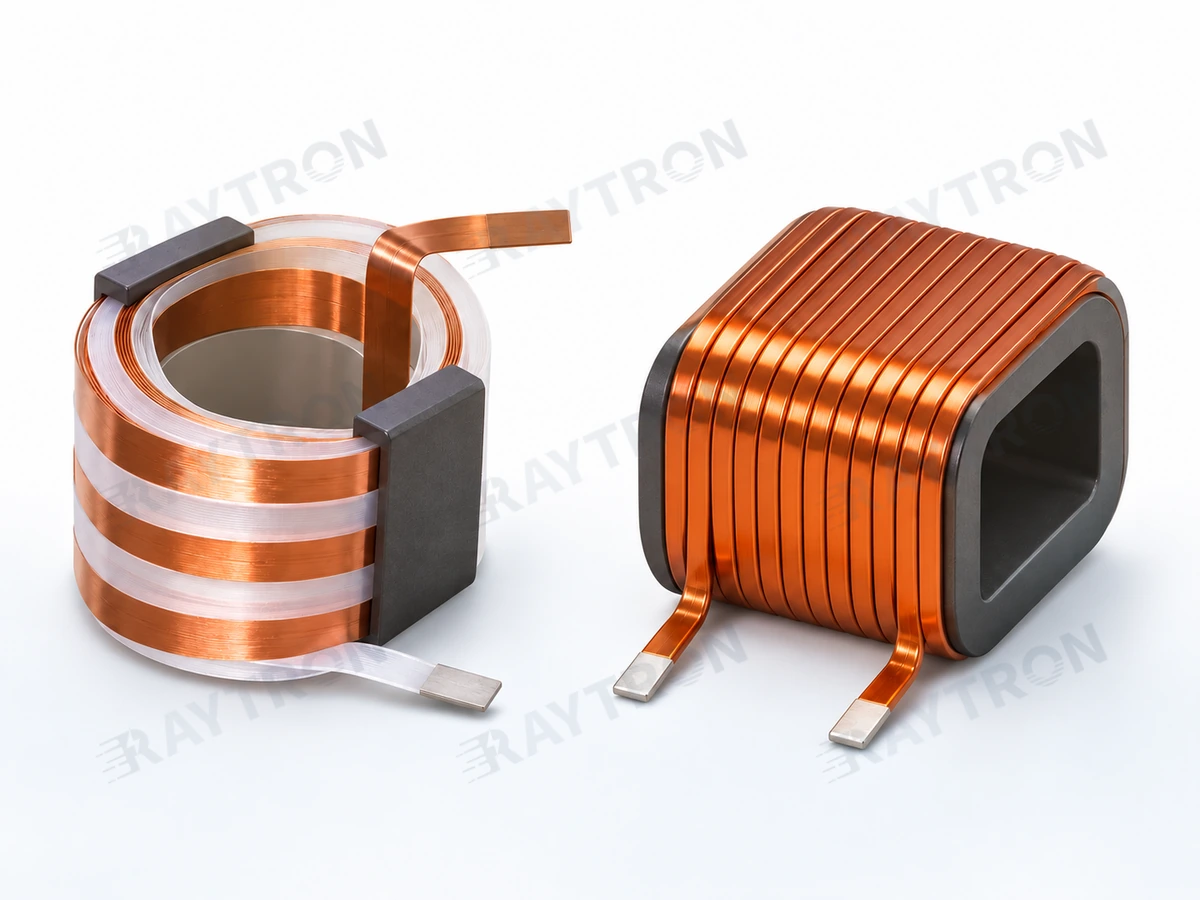
Separate RMS and peak current, frequency content, insulated space and thermal limits. DC resistance and AC losses require different measurements under the stated duty.
Related conductor products
Design and testing
- Electrical duty
- Specify frequency spectrum, waveform, RMS and peak current, turns, allowable loss and winding temperature rise.
- Winding construction
- Define foil thickness and width or flat-wire section, insulation, edge condition, winding tension and terminations. Compare resistance at a stated temperature.
- Validation and supply
- Agree DC and AC loss measurements, thermal cycling, insulation tests and joint acceptance for the assembled component; confirm material and insulation availability.
Application design factors
Inductor and transformer windings combine conductor geometry, insulation, switching duty and thermal design.
Application design record — open worksheet
Record your project requirements and observations, then download or include them in an inquiry.
| Item | Information / units | Your input |
|---|---|---|
| Magnetic component | Inductor/transformer, drawing, turns/window and insulation envelope | |
| Operating basis | Frequency, waveform, current, duty and temperature; distinguish core and winding losses | |
| Trial | Actual geometry, bend/edge/insulation checks, joints, loss/temperature-rise methods and acceptance records |
Other formats and preview
Save or restore a draft
Drafts stay in this browser. Clear inputs also removes the saved draft.
Worksheet version: RT-RFQ-WORKSHEET-1.
Does equal DC resistance establish equal inverter winding loss?
No. AC current distribution, proximity effects, winding arrangement and temperature influence loss. Measure or calculate the actual winding at the specified waveform and confirm the model with component testing.