
01 Decide in one minute whether CCA is worth evaluating
If the weight, cost per metre, or supply cost of your copper material is a problem, and your product allows a change in material or section, CCA deserves a place on the shortlist. Answer these six questions before ordering samples.
| First establish | Why it matters |
|---|---|
| What the material does in the product | Carrying current, transmitting signals, soldering, making contact, and shielding have different priorities |
| Where the product will be sold and which specifications apply | Determines whether the material is permitted and which finished-product tests and approvals are needed |
| What cannot change | Diameter, thickness, terminals, tooling, resistance, temperature rise, or the customer drawing |
| How the material will be processed and joined | Drawing, rolling, stamping, bending, coating, soldering, welding, or crimping |
| Operating conditions | Continuous current, frequency, flexing, temperature, moisture, and chemical exposure |
| The unit used to compare cost | Per metre, per part, or per accepted module, including yield and associated costs |
The most productive projects have clear requirements, clear acceptance criteria, and a cost comparison that can be checked after the trial.
02 What copper-clad aluminum is
Copper outside, aluminum inside, both carrying current
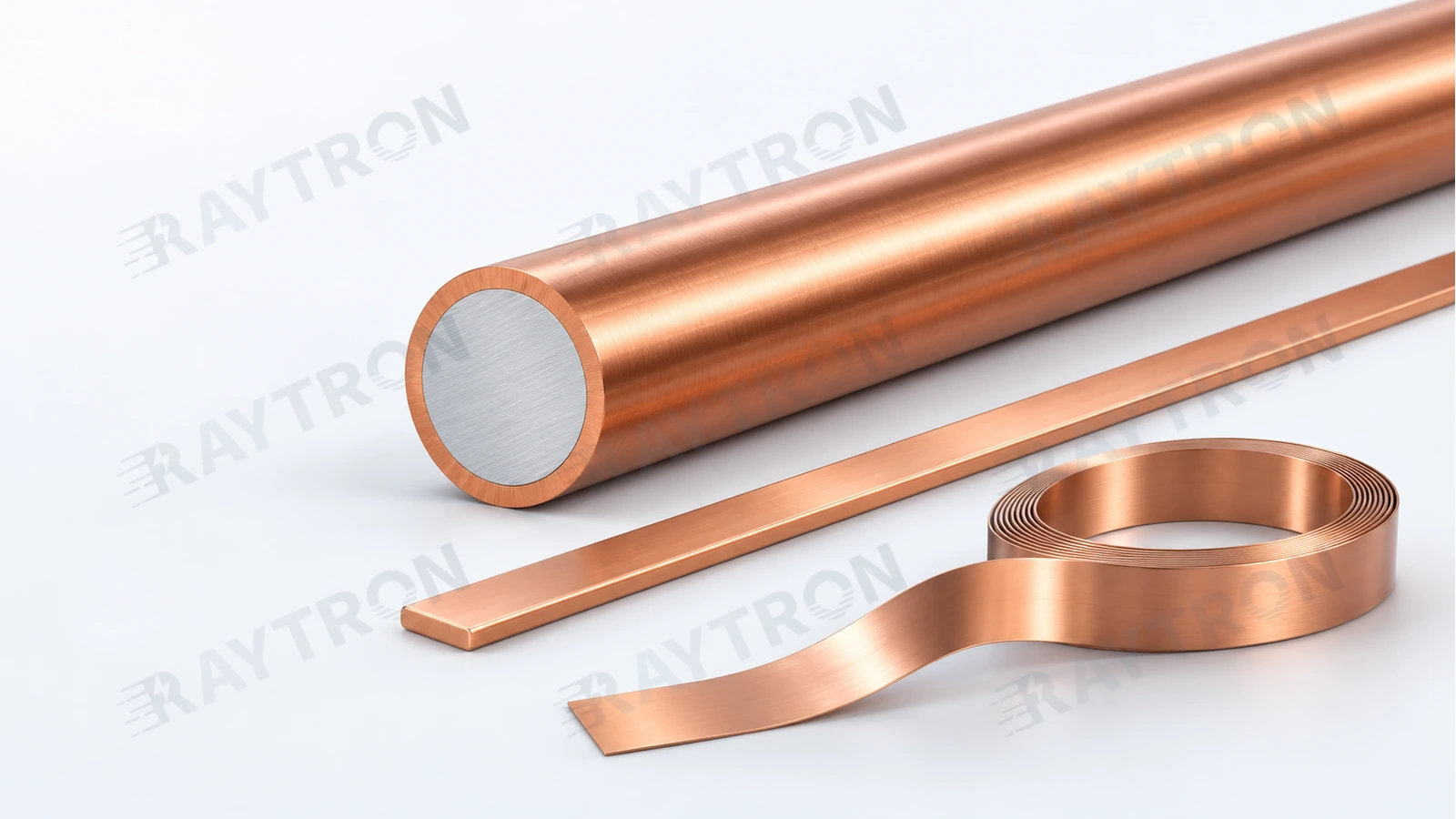
Typical CCA wire has an aluminum core surrounded by continuous copper cladding. Copper provides the external contact surface and conducts current. The aluminum core reduces weight and also conducts current. Calling it merely a filler misses a substantial part of its job. [R01][R17]
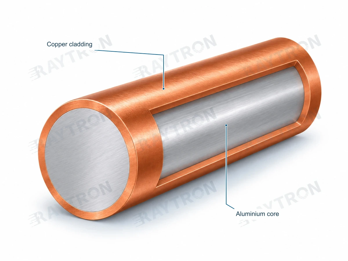
This is a composite structure: copper and aluminum remain distinct material regions. It is different from melting the two metals together to make an alloy.
On the market, “alloy ribbon” may refer to an alloy core, a solder formulation, or another material system. When names sound similar, check the cross-section and composition first.
A silvery aluminum core visible at the cut end of a round wire is normal. Exposed aluminum, cracked copper, or separation along the outside of a wire specified as fully clad calls for inspection against the agreed requirements. Colour can help identify a construction; it cannot complete an acceptance test.
Turn product names into actual specifications
| Name | What it usually describes | What the buyer still needs to establish |
|---|---|---|
| CCA | Copper-clad aluminum | Copper fraction, aluminum core grade, temper, dimensions, and resistance |
| CCAA / HTCCA | Copper cladding over a specified aluminum-alloy core; HTCCA is a Raytron product-family name | Actual core grade and performance; the abbreviation alone does not establish high-temperature capability or an AA-8000-series core |
| Tinned CCA | A CCA substrate with an additional tin or solder coating | Coating composition and thickness, bare or coated dimensions, and soldering compatibility |
| CCA flat wire, strip, or foil | Different supplied forms of a copper-aluminum composite | Cross-section, copper-covered faces, edges, and the width–thickness combination |
| CCS | Copper-clad steel | The steel core's mechanical, electrical, and magnetic properties; CCS and CCA are not interchangeable |
| Polymer-based composite copper foil | Copper layers combined with a polymer core | A different structure and application from metal-core CCA foil |
“High strength,” “high conductivity,” and “extra soft” are useful introductions. Before signing an order, replace them with values, units, and test conditions.
03 What CCA can offer
Less weight and a cost per metre worth calculating
Copper and aluminum have very different densities. The teaching calculations in this guide use 8.96 g/cm³ for copper and 2.70 g/cm³ for aluminum. The density of the delivered material depends on its actual core, copper fraction, and coating. [R04][R05]
At the same section and length, CCA is generally much lighter than copper. Some weight advantage may remain even when the section is increased to reduce resistance. To determine the cost benefit, multiply actual mass by the quoted finished-material price, then account for processing and associated components.
The copper surface is useful, and the whole section matters
A copper surface has practical value for connections, soldering, and certain high-frequency designs. It does not give the underlying aluminum all the properties of solid copper. At equal dimensions, CCA generally has higher DC resistance than copper. Electrical duty, connections, mechanics, and environmental performance belong in the same design review.
Design flexibility has value too
Copper fraction, core material, temper, round or flat geometry, and coating can all be design variables. Where a product allows these to change, there is usually more room to find an economical construction than when every dimension and process must remain fixed.
CCA earns its place through the cost, weight, and manufacturing performance of an accepted product. The material quotation is only the first bill.
04 Always ask what the copper percentage means
“30% copper” is not a complete specification. It could mean copper by mass or by volume. Leaving out a few letters can add three meetings.
This guide primarily uses copper volume fraction, vol.%, when comparing materials. For uniform bare material over the same length, copper cross-sectional area fraction equals copper volume fraction. Copper mass fraction is written as wt.%.
Volume fraction and mass fraction are different
The following calculations use copper at 8.96 g/cm³ and aluminum at 2.70 g/cm³, with no coating. They explain the relationship between fractions; they are not an availability table.
| Copper volume fraction, vol.% | Corresponding copper mass fraction, wt.% | Calculated density, g/cm³ |
|---|---|---|
| 10 | 26.94 | 3.326 |
| 15 | 36.93 | 3.639 |
| 30 | 58.72 | 4.578 |
| 40 | 68.87 | 5.204 |
| 50 | 76.84 | 5.830 |

Working the other way, 30 wt.% copper is approximately 11.44 vol.%; 40 wt.% is approximately 16.73 vol.%; and 50 wt.% is approximately 23.16 vol.%. 30 wt.% and 30 vol.% describe different compositions.
Some existing Raytron designations, such as “CCA30,” use copper mass fraction. State the actual fraction and its basis in the purchase specification instead of inferring them from the grade name. For tinned products, also state whether the percentage applies to the substrate or to all metal in the coated product.
More copper is not automatically better value
With the same core material, temper, and substrate dimensions, increasing the copper fraction generally increases conductivity and copper thickness, while also increasing density and material cost. The objective is a suitable composition that meets the resistance, connection, forming, and reliability requirements.
At minimum, specify the fraction basis, nominal value or limits, core material, treatment of coatings, and inspection method.
ASTM B566 classes 10A, 15A, 10H, and 15H refer to nominal copper volume fractions of 10% or 15%. A denotes annealed and H denotes hard-drawn. In this context, “10A” does not mean ten amperes. [R01]
05 Understand resistivity, conductivity, and ampacity
Three measurements that answer different questions
| Property | Plain-language meaning | How to specify it |
|---|---|---|
| Resistivity | How strongly the material resists current; usually lower is better | At 20°C, in Ω·mm²/m, identifying whether the area is bare metal or the finished section |
| Resistance | The resistance of an actual conductor length; depends on length, section, and temperature | Single conductor or complete circuit, Ω/km or Ω/m, and measurement temperature |
| Ampacity | Permitted continuous current under defined conditions | Together with insulation, ambient conditions, installation, bundling, connections, and permitted temperature |
IACS is a conductivity reference. At 20°C, 100% IACS corresponds to approximately 0.017241 Ω·mm²/m. [R03]
70% IACS does not mean “70% of copper's current rating,” nor does it permit automatic use of copper ampacity tables. Temperature rise depends on the balance between heating and cooling. A connection can become the limiting point before the conductor itself does.
A transparent teaching model
Assume copper at 100% IACS and aluminum at 61% IACS, both metals effectively connected to the current path, a continuous interface, and a uniform section. Compare straight bare conductors of the same length at 20°C. The values below are calculated using these assumptions. [R03]
| Copper volume fraction | Theoretical conductivity, %IACS | Area multiplier for equal resistance | Round-wire diameter multiplier | Mass at equal resistance, relative to copper |
|---|---|---|---|---|
| 10% | 64.90 | 1.541 | 1.241 | 57.2% |
| 15% | 66.85 | 1.496 | 1.223 | 60.8% |
| 30% | 72.70 | 1.376 | 1.173 | 70.3% |
| 40% | 76.60 | 1.305 | 1.143 | 75.8% |
| 50% | 80.50 | 1.242 | 1.115 | 80.8% |
Multipliers and mass ratios use an equal-length copper conductor as the reference. The model shows why CCA generally needs a larger section to achieve similar DC resistance, yet may still weigh less. Alloy cores, material condition, coatings, and actual dimensions affect the result.
Power frequency and high frequency need separate treatment
“The current only travels through the copper skin, so it performs like copper” does not describe DC operation. It is also unsuitable as an explanation for common small-diameter wires at 50/60 Hz.
At higher frequencies, current concentrates closer to the surface, making copper-layer design useful. Performance still depends on frequency, minimum copper thickness, conductor geometry, surface condition, proximity effect, and connections. For ideal nonmagnetic copper, skin depth is approximately 9.35 mm at 50 Hz and 66 μm at 1 MHz. These values describe the skin depth of copper under the stated conditions.
The skin-depth calculation assumes copper at 20°C and 100% IACS, with relative magnetic permeability approximately 1. The NIST reference provides the relevant formula and order of magnitude. [R27]
For RF products, evaluate insertion loss, return loss, and the complete assembly. Windings also need AC-loss assessment at their operating frequency. Equal DC resistance answers one question; it does not complete the equipment evaluation.
06 Choose the right form of wire, strip, or foil
| Form | Geometry to specify first | Frequently overlooked details |
|---|---|---|
| Round wire | Diameter, tolerance, ovality | Cladding eccentricity, thinnest copper location, continuous reel length |
| Fine flat wire | Thickness × width, corner radii, permitted cross-sectional area | Copper at rolled edges and corners, bend direction, springback |
| Strip | Thickness × width, camber, flatness | Slitting burrs, edge coverage, core exposure after stamping |
| Foil | Total thickness, copper-layer construction, thickness uniformity | Pinholes or defects, winding and unwinding, core dimensions, winding tension |
| Tinned or solder-coated product | Separate substrate and finished dimensions | Coating composition, local thickness, soldering, and storage requirements |
Suppliers and standards may use different thickness boundaries for “strip” and “foil.” A dimension in millimetres or micrometres is more useful on a drawing than a debate over the name.
Reference ranges on Raytron's current product pages
The published reference diameter for round wire is 0.10–4.00 mm. Some flat-wire pages give a reference width limit of 6 mm. Precision CCA strip and foil pages list widths of 0.5–12 mm. [R17][R18][R19]
These are ranges for different product forms. Do not combine the maximum width, minimum thickness, thinnest copper layer, and tightest tolerance into an assumed deliverable specification. Send the actual width–thickness combination or drawing so Raytron can confirm material, temper, surface, reel length, and tolerances together.
Identify every face that needs copper coverage
Flat material rolled from fully clad round wire can have a different edge structure from a two-sided Cu/Al/Cu laminate. Mark the required copper coverage on the upper face, lower face, edges, and joining locations.
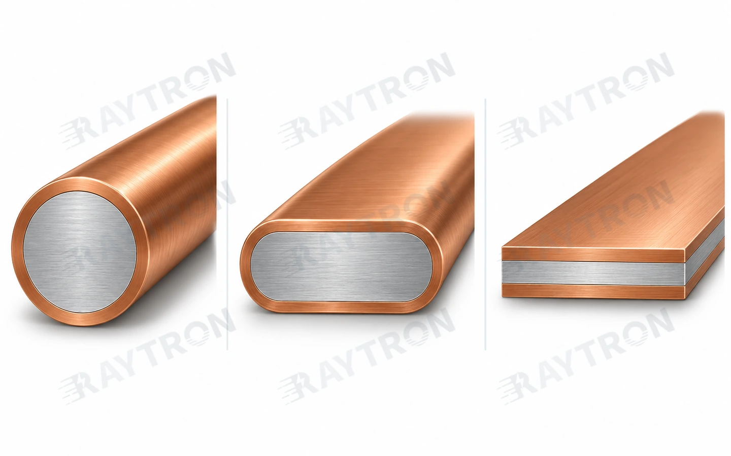
Fully clad as delivered does not mean that every new face created by slitting, punching, or cutting will also be copper-covered. Processing exposes new sections. Their connections and environmental exposure need to be considered. [R18][R19]
The words “copper foil” in a product description do not make CCA foil a direct substitute for a solid-copper battery current collector, any width of shielding foil, or PCB copper foil. Confirm construction, width, intended duty, and finished-product requirements first.
Resistance measured after coating, combined with the total coated metal cross-sectional area, gives the finished product's equivalent resistivity. It cannot be treated directly as the bare substrate's resistivity. For coated products such as PV ribbon, prioritise an agreed finished resistance per metre.
07 Look beyond average copper thickness
The same overall copper fraction can be distributed differently around a section. An acceptable average fraction does not establish equal thickness in every direction. Edges, corners, rolling transitions, and contact locations deserve particular attention in flat products.

For an ideal concentric round wire with substrate outside diameter D, excluding any added coating, and copper volume fraction f, radial copper thickness is:
t = D ÷ 2 × [1 − √(1 − f)]
At a 1.00 mm outside diameter, ideal copper thickness is approximately 25.7 μm at 10 vol.% copper and 39.0 μm at 15 vol.%. At a 0.20 mm diameter, those thicknesses become approximately 5.1 μm and 7.8 μm. The percentage can stay the same while the absolute copper thickness becomes much smaller.
This formula cannot be applied directly to rolled flat material. Determine the actual minimum layer thickness from a real cross-section with a scale, using agreed sampling locations, calculation methods, and acceptance limits.
If a specification says “relative copper-thickness deviation ≤ X%,” ask what the denominator is: average thickness, nominal thickness, or another reference? The same label can conceal different calculations. Put the formula in the technical agreement so the numbers can be compared.
08 Understand the process and ask for measurable results
Copper-aluminum composites can be made by different manufacturing routes. Buyers do not need to memorise every process, but they should understand which steps affect the delivered product.
| Process stage | Why it matters to your product | Useful evidence to request |
|---|---|---|
| Core and copper feedstock | Establishes basic electrical, mechanical, and processing behaviour | Material grades and lot records |
| Surface preparation and bonding | Affects interface continuity and subsequent deformation | Actual cross-sections and bond tests suited to the product form |
| Drawing and rolling | Changes dimensions, copper distribution, surface, and material condition | Dimensional and resistance records; sections at critical locations |
| Heat treatment | Changes temper, elongation, and interface structure | Mechanical, electrical, and downstream-processing results for the actual specification |
| Coating and winding | Affects joining, storage, and production-line handling | Coating, surface, packaging, and payoff requirements |
Raytron's published process information connects material preparation, composite forming, heat treatment, and inspection, with the route and acceptance method established for the particular product. [R21]
Heat treatment must suit the materials and process. Excessive interfacial reaction, defects, and local damage can affect performance. The best temperature reported in one paper is not an annealing recipe for every product. [R24]
Process labels such as “electroplated,” “clad,” or “rolled” do not rank every product by quality. A more useful purchasing question is whether the actual construction meets its specification and continues to do so after your bending, soldering, crimping, or thermal cycling.
09 Match the evaluation to the application
This table identifies selection priorities. It is not a worldwide approval list.
| Application | Potential value to evaluate | What to check first |
|---|---|---|
| PV module interconnects and busbars | Reduced copper use and ribbon purchasing cost | Finished resistance, stringing, yield, module power, and reliability |
| Coaxial cables and antennas | Lower weight, with RF performance designed around the copper surface | Frequency, copper thickness, attenuation, impedance, terminations, and complete-cable requirements |
| CAT 5e / CAT 6 network-cable conductors | Established large-scale use to reduce conductor weight and material cost | Finished-cable transmission performance, DC resistance and unbalance, terminations; voltage drop and temperature rise for PoE |
| Cable shielding tape | CCA strip is being used to replace copper tape for weight and material-cost reduction | Shield function, copper-layer construction, thickness, width, overlap, continuity, and connections; short-circuit capability where fault current is carried |
| Metallic screen wire for MV cables | A balance of resistance, weight, and cost in permitted constructions | Screen resistance, fault current and duration, connections, and customer specifications |
| LV concentric neutrals or service cables | Specific application routes exist in some utility specifications | Installed role, construction, document revision, short-circuit duty, and finished-cable assessment |
| Building wire | Development where the destination market provides a compliance route | Core material, material and cable certification, wire size, terminals, and locally adopted rules |
| Track-light and equipment conductors | Section and cost options within a limited envelope | Current, contact pressure, temperature rise, wear, and equipment requirements |
| Electronic connection strips and narrow foil parts | Weight reduction and material-construction options | Stamping, bending, joining, exposed core edges, and contact stability |
| Windings and electromagnetic components | Weight and cost options where the design can change | Slot fill, DC and AC losses, insulation, temperature rise, and lead connections |
| Frequently flexed cables or welding cables | Development around a specific cable construction | Flexibility, strand fatigue, duty cycle, temperature rise, terminals, and product standards |
HARADA's official history records the development of a CCA coaxial cable in 2008. This establishes an application history in coaxial products; it does not establish direct substitution in every coaxial construction or indicate that HARADA uses Raytron material. [R23]
CAT 5e / CAT 6 network cable: select the conductor and cable together
CCA conductors are already used at large scale in CAT 5e and CAT 6 network cables. For cable manufacturers, this is an established material-selection route for reducing conductor weight and material cost. [R30]
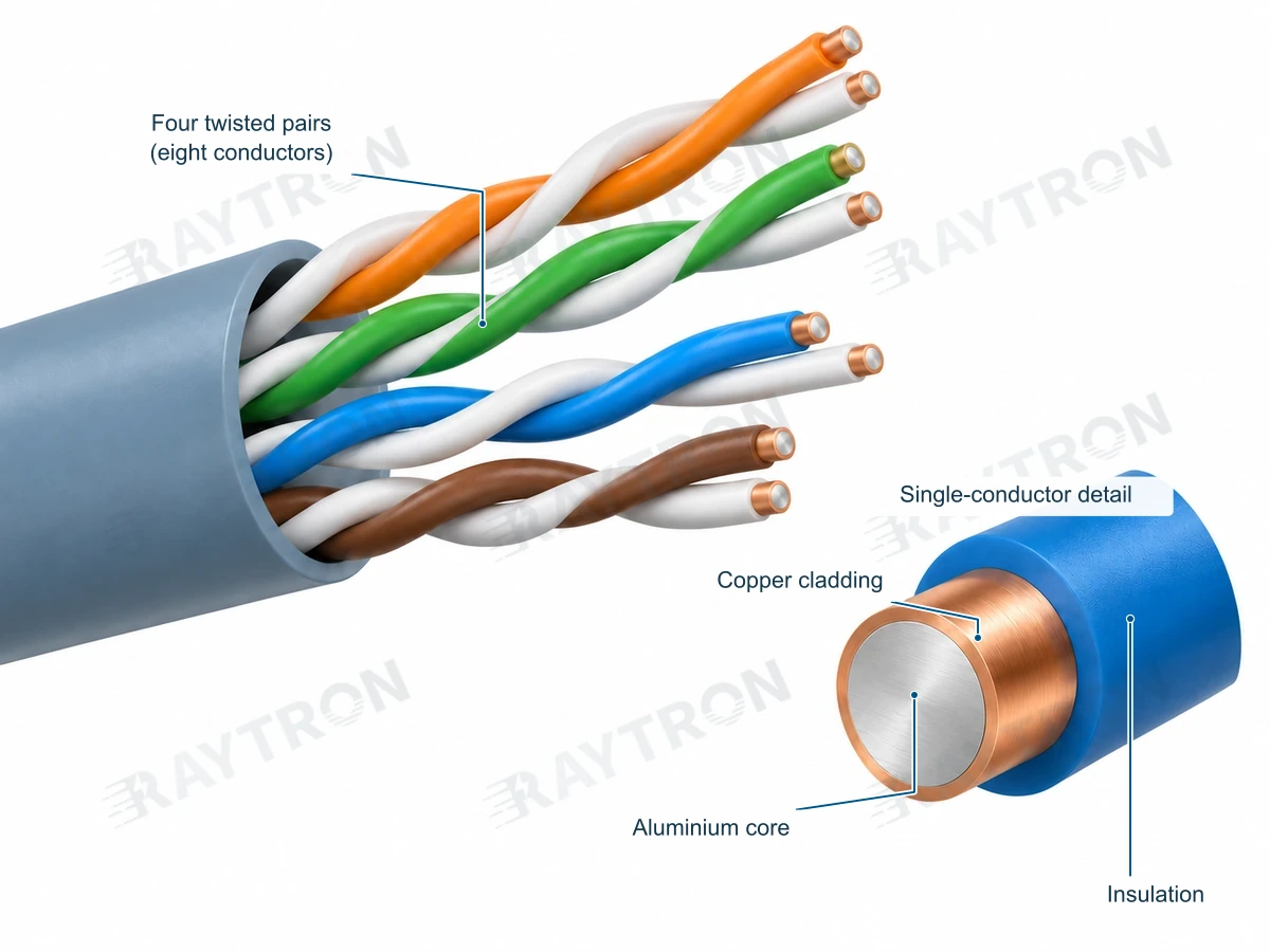
Select wire diameter, copper volume fraction, core material, and temper together with insulation, pair twist, and terminations. Inspect the conductor for dimensions, DC resistance at 20°C, mechanical properties, and copper cladding. Test the finished cable for insertion loss, return loss, crosstalk, and resistance unbalance at the agreed category, frequency range, and length. The signal needs to get through, and the pairs need to stay out of each other's way.
For PoE, also specify power level, link length, loop voltage drop, bundled-cable temperature rise, and connectors. Data-only service and combined data-and-power service have different acceptance priorities.
State CCA conductors, test methods, limits, and intended use explicitly in the order. Projects requiring compliance with specified TIA, ISO/IEC, or local installation requirements must also address the relevant conductor-material provisions and certification. Record the test category, length, and test items: a statement that a cable passed a 100-metre test should refer to an actual report and does not establish every compliance requirement. [R13]
Cable shielding tape: replacing copper tape with CCA strip
CCA strip is now being used to replace copper tape in cable shields. [R30] This is a copper-aluminum metallic composite; distinguish it from aluminum/polymer and copper/polymer laminates when specifying the construction. A shielding tape and the cable's core conductors are also different components and must be selected for their respective functions.
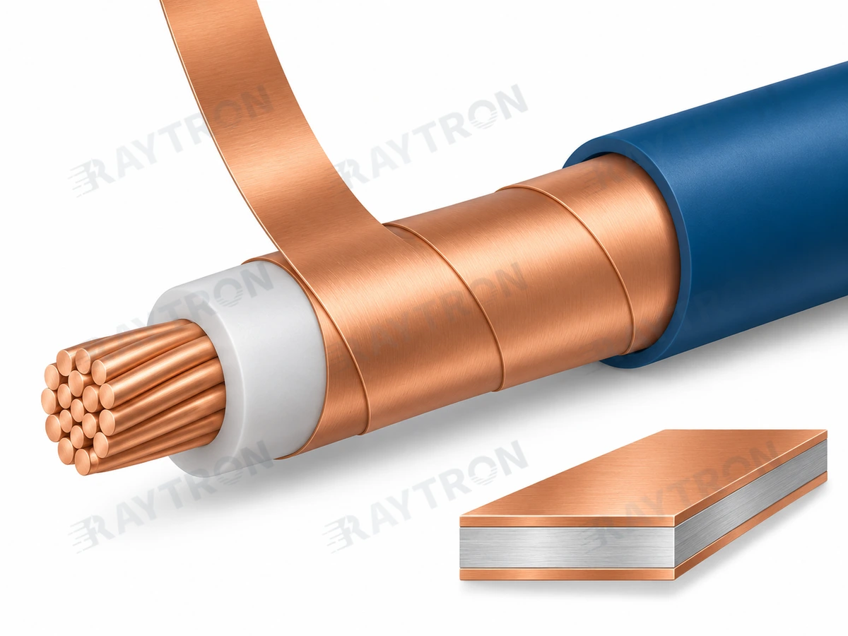
Start with the shield's job. For signal or electromagnetic shielding, specify the frequency range, helical or longitudinal wrapping method, coverage and overlap, shield continuity, and drain-wire or connection arrangement. Assess shielding performance in the finished cable. If a power-cable metallic screen also carries earth-fault current, assess screen resistance, effective metallic cross-section, fault current and duration, permitted temperatures, and earthing connections. One construction may perform both jobs and must meet both sets of requirements.
Then specify the strip and wrapping conditions. Include thickness × width, tolerances, copper volume fraction or specified layer construction, minimum copper thickness, temper, edge burrs, bond integrity, and overlap width or percentage. Define how overlap percentage is calculated. The drawing should also identify contact and protection requirements at slit edges, joints, and earthing points.
Compare actual tape consumption per kilometre of finished cable, including thickness, width, wrapping pitch, overlap, process losses, and connection costs. Equal tape thickness does not establish equal shielding performance or equal short-circuit capability. Validate the substitution in the finished cable and calculate cost on the same construction basis.
Resolve these constraints before ordering substitution samples
The customer drawing may require copper without permitting a material change. The material or finished-product specification may provide no applicable route. Dimensions may be fixed while resistance has no remaining margin. Or the connection and environment may be impossible to validate. Resolve the relevant constraint before beginning a replacement trial.
10 Compare the PV ribbon bill and the module result together
Purchasing, process engineering, R&D, and quality look at different aspects of the same ribbon. Purchasing needs lower cost; process engineering needs stable stringing; R&D checks power; quality checks cell damage, connections, and long-term reliability. A useful evaluation brings these measures into one comparison. [R20]
The material-cost opportunity
Some projects reduced ribbon material cost by more than 50% using copper-aluminum composite ribbon instead of copper ribbon. The percentage refers to ribbon material cost. Calculate your project's saving from its specification, purchase price, actual consumption, and yield. [R22]
A saving needs a denominator. A 50% reduction in ribbon cost does not mean a 50% reduction in total module cost. Savings per GW also depend on the corresponding production volume, actual ribbon consumption, and module output.
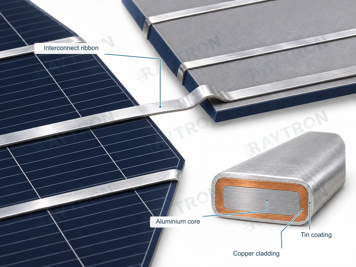
Raytron's copper-aluminum composite ribbon has been used in more than 50 GW of modules cumulatively. [R29]
Record five groups of results
| Data group | Minimum useful records |
|---|---|
| Material | Substrate and coated dimensions, copper fraction, finished resistance per metre, yield or proof strength, and elongation |
| Joining | Solder composition, flux, temperature profile, pull or peel method, and joint consistency |
| Production | Stringing speed, downtime, ribbon breaks, rework, cell breakage, and accepted yield on a consistent measurement basis |
| Module | Electroluminescence results, power distribution, and relevant contact- and series-resistance behaviour |
| Reliability | Thermal cycling, damp heat, and other applicable tests selected for the product and certification requirements, including electrical and visual results after testing |
Names such as MBB, SMBB, 0BB, BC, and HJT do not define a ribbon specification on their own. Establish the cell construction, interconnection layout, contact locations, process temperature, and equipment before selecting the substrate and coating. Fine-wire and low-temperature processes need particular care when carrying settings over from an earlier product.
“Tinned” does not automatically mean pure tin, lead-free, or compatible with every soldering process. State the actual solder composition, thickness, and environmental requirements. Measure and specify the copper layer separately from the solder coating.
Compare cost per watt on a consistent basis
Ribbon material cost per watt = ribbon material cost attributable to one accepted module ÷ that module's actual output power.
For a complete-module comparison, use the full module cost on the same basis, including yield, process changes, and actual output. A ribbon saving cannot simply be relabelled as a percentage reduction in complete-module cost per watt.
Likewise, a measured power difference in one project is not a fixed wattage loss for every module. A useful comparison uses the same cell batch, module construction, and test conditions.
Agree the retesting scope for module design changes with the certification body. IEC TS 62915:2023 provides a retesting framework related to IEC 61215 and IEC 61730. Passing design qualification does not translate directly into a specified number of years of actual service life. [R14][R15][R16]
11 Follow the applicable route for utility cables and building wire
Three documented utility examples
| Source | What can be established | How a buyer should use it |
|---|---|---|
| ENEL GSCC014, amendment 01/2025 | Introduces CCA concentric neutral conductors for certain Type I–III LV concentric cables for Italy; Types II/III still require copper equalising tape | Develop against the specific cable type, installed position, conductor resistance, and project documents |
| EPM ET-TD-ME01-18 Rev.2, 2018 | A historical public specification includes CCA concentric service cables; the CENS directory marks the specification as being updated | Use as an application lead and ask the customer for the current controlled revision |
| Eskom 240-56063805 Rev.3, 2022 | Provides pilot or trial routes for certain CCAA LV service cables and multicore LV control cables | Follow the specified pilot, project dimensions, and approval conditions |
Develop each project against the relevant utility's cable type, document revision, and approval procedure. [R09][R10][R11][R12]
MV metallic screen wire must address fault duty
A metallic screen may carry fault current as well as meeting normal resistance requirements. Establish fault current, clearance time, permitted initial and final temperatures, screen construction, and earthing connections. Do not apply copper's short-circuit thermal constant directly to a composite conductor.
For example, if a customer requires resistivity below 0.027 Ω·mm²/m at 20°C, conversion using the 100% IACS reference gives conductivity above approximately 63.86% IACS. This is a conversion of a stated technical requirement, not a universal utility limit. Acceptance should still use the original limit, measurement uncertainty, and agreed decision rule.
US building wire requires a complete compliance route
CCA has a compliance route in US building wiring, but adding insulation to ordinary bare CCA does not automatically establish suitability. Core material, cladding, material and finished-cable certification, wire size, protective devices, terminals, and the code edition adopted at the project location must work together. [R07][R08]
Other markets also require a review starting from the finished product. Compliance with a material standard, a satisfactory resistance test, or a quality-management certificate does not replace the destination product's requirements.
12 Connections and environment determine service performance
Crimped and bolted connections
Confirm the connector's permitted conductor material, wire size, solid or stranded construction, temperature rating, tools, dies, and installation settings. Use the specific certification and manufacturer's instructions to establish suitability. A copper surface alone is not enough. [R07][R25]
Beyond initial resistance and pull-out strength, evaluate connection stability after thermal or current cycling as required by the application. If an antioxidant compound is required, follow the connector instructions; do not add an arbitrary grease or paste.
Joining and forming
Identify the surface actually being joined, whether processing leaves the copper layer intact, and how heat input affects the substrate and coating. Making one joint does not establish a stable production window. Butt, lap, ultrasonic, resistance, and laser joining processes should be developed for the actual material combination.
For bending, define radius, direction, number of cycles, speed, and acceptance criteria. Higher elongation in an annealed material does not by itself establish high-cycle flex life.
Moisture and corrosion
Continuous copper cladding changes the exposed surface, but cut ends, punched edges, scratches, and locations where water can enter still need assessment. Where an electrolyte, copper-aluminum contact, and local exposure are present, consider galvanic corrosion and address it through sealing, connection, or protection measures appropriate to the environment. [R26]
Select salt-spray, damp-heat, or immersion tests for the intended service. An isolated number of test hours cannot be converted directly into years outdoors.
13 Calculate cost per metre, per part, and per accepted output
Finance pays by the kilogram. The product works by the metre. Both need to be happy.
Step one is to fix the comparison basis
| Comparison route | When it is useful | Main issues to evaluate |
|---|---|---|
| Keep the dimensions | Tooling, slots, or the external envelope cannot change | Increased resistance, temperature rise, and operating margin |
| Keep the DC resistance | A larger section is possible | Dimensions, mass, terminals, insulation, and processing cost |
| Redesign the component | Material, geometry, or construction can change | Complete-product performance and cost per accepted part |
Do not combine the weight saving from the first route with the electrical performance of the second and present them as one product.
Step two is a calculation anyone can check
Compare 1 km of straight bare conductor at 20°C. Assume copper with an area of 2.50 mm², resistivity of 0.017241 Ω·mm²/m, and density of 8.96 g/cm³. Assume CCA with resistivity of 0.027 Ω·mm²/m and density of 3.42 g/cm³. These are separate teaching inputs, not a grade from the earlier ideal-composition table or guaranteed properties of a Raytron product.
| Measure | Copper reference | CCA at equal area | CCA at equal resistance |
|---|---|---|---|
| Metal area, mm² | 2.500 | 2.500 | 3.915 |
| Single-conductor resistance, Ω/km | 6.896 | 10.800 | 6.896 |
| Mass, kg/km | 22.400 | 8.550 | 13.390 |
| Weight reduction versus copper | Reference | 61.8% | 40.2% |
| Change in round-wire diameter | Reference | None | Approximately 25.1% larger |

Insert the actual finished-material prices: P_Cu for copper and P_CCA for CCA, both in the same currency per kg and on matching tax and delivery terms. Material cost per kilometre is respectively 22.400 × P_Cu, 8.550 × P_CCA, and 13.390 × P_CCA.
In this example, even at the same price per kilogram, the equal-resistance CCA option reduces conductor material purchasing cost by approximately 40.2% because less mass is required. For a real project, recalculate using the price and mass of the corresponding specification, then include the associated costs below.
Step three is to include the rest of the bill
| Cost item | Use these inputs |
|---|---|
| Material purchasing | Finished-material price × actual purchased mass, with consistent currency, tax, and delivery terms |
| Yield and scrap | Actual trial input, accepted output, and recoverable scrap value |
| Customer processing | Speed, wire breaks, downtime, labour, joining, and rework |
| Associated materials | Changes in insulation, sheath, terminals, solder, adhesive, seals, and other parts |
| One-time investment | Tooling, equipment changes, qualification, and certification, spread over expected usable production volume |
| Logistics and financing | Actual changes in freight, packaging, inventory, and payment terms |
| Service phase | Where relevant, electrical losses, maintenance, and replacement under the same conditions and period |
Net material cost per accepted part = (input material cost − recoverable scrap value) ÷ number of accepted parts.
Leave an unknown cost as an open item. “Unknown” and “zero” are different numbers.
Read a metal-price-plus-conversion-charge quotation correctly
When a quote uses copper and aluminum metal prices plus a conversion charge, weight the metal prices by mass fraction. Establish the metal-price source, date or price-fixing rule, currency, tax basis, losses, and items included in the conversion charge. Volume fractions cannot be multiplied directly by metal prices per tonne.
Confirm whether coatings, special packaging, and additional processing are included. A valid comparison brings finished prices on the same basis together with actual consumption.
14 Move from samples to production with a clear trial plan
First record the baseline
Document the existing copper specification, drawing, actual resistance, processing settings, accepted yield, and current cost. Without a baseline, an equipment change can easily be mistaken for a material effect.
Then work through four steps
- Screen the options on paper. Confirm permitted materials, available space, resistance target, connection method, and destination market. Select a small number of meaningfully different candidates.
- Inspect material samples. Check dimensions, resistance, copper layers, and mechanical properties. Match each sample lot to its inspection report.
- Run the real production process. Use the intended equipment, terminals, solder, and operating conditions. Record speed, defects, yield, and product performance.
- Approve and scale up. Complete the applicable reliability work and approvals. Freeze the drawing, inspection requirements, packaging, and change-notification requirements before production supply.
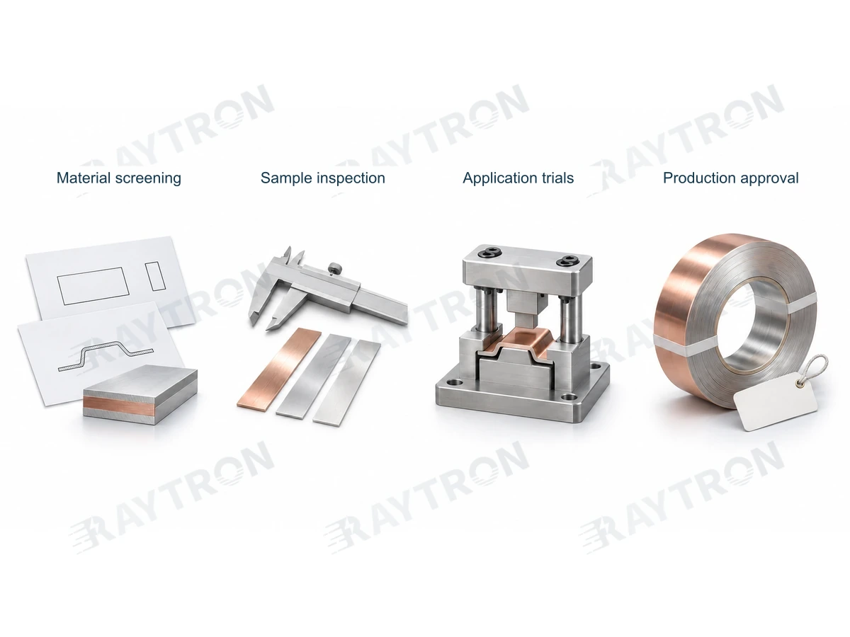
Agree pass criteria before the trial. Results should identify which requirements were met and which need adjustment, rather than ending with “seems fine.”
A supplier's free sample is useful, but it is still a sample. What you ultimately buy is the ability to deliver the agreed result again, lot after lot.
15 Build an incoming-inspection checklist
The following is a framework for an acceptance agreement. Limits, sampling, and frequency should come from applicable standards and mutually agreed requirements. This example is not a universal mandatory test specification.
| Item | How to check | Minimum report content |
|---|---|---|
| Identity and traceability | Cross-check labels, order, reel identity, and lot number | Material, specification, temper, lot, and delivered quantity |
| Dimensions | Measure diameter or width and thickness at agreed locations | Actual values, tolerances, bare or coated condition, instrument, and sampling |
| DC resistance | Suitable four-wire or specified method, with controlled length and temperature | Original resistance, length, temperature, conversion basis, and units |
| Copper fraction and layers | Metallographic section analysis, with agreed composition methods where needed | Fraction basis, scale, location, minimum thickness, and average |
| Interface and continuity | Sections, bending, torsion, peel, or shear tests suited to the product form | Method, load or geometry, acceptance criteria, and results |
| Mechanical properties | Tensile and applicable forming tests | Tensile strength, elongation, gauge length, and Rp0.2 where needed |
| Coating | Composition, thickness, and coverage checks | Substrate and coating identified separately; local or average thickness |
| Surface and edges | Inspect scratches, cracks, burrs, contamination, and exposed core | Defect position, size, and agreed permitted conditions |
| Actual connection | Make joints using the production joining method | Initial and specified post-ageing resistance, strength, or temperature rise |
| Packaging and quantity | Check mass, length, core dimensions, and payoff | Net mass, tare, length, joints, and winding direction |
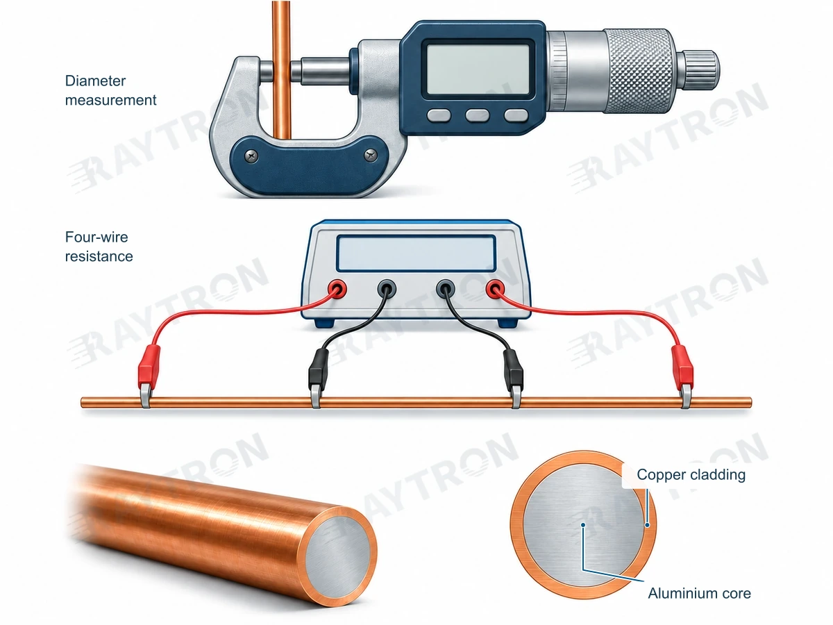
Common inspection traps
A handheld instrument identifying copper at the surface does not establish that the entire conductor is copper or determine its overall copper fraction. Surface composition and cross-sectional composition are different questions.
Mass alone cannot establish copper content. Length, section, coating, reel tare, and core material all affect the result. Weighing is useful as a cross-check.
A magnet generally cannot distinguish copper from CCA. A lack of magnetic attraction does not prove a conductor is solid copper.
An attractive cross-section image represents the sampled location. Agree representative sampling for new suppliers, changed products, and important lots. Whether samples come from the beginning, middle, or end of a reel, or from different reels, should reflect the process and relevant risks.
Qualification testing and routine release inspection can be separate. Every reel need not repeat every long-duration test, but production inspection must detect changes that affect delivery.
Control temperature when measuring resistance. Conversion to 20°C requires a correction appropriate to the material and method; copper's temperature coefficient cannot be applied indiscriminately to every composite. ASTM B193-25 provides a method for measuring the resistivity of metallic conductors. [R28]
A surface eddy-current conductivity reading and the longitudinal DC resistance of a conductor length are different measurements. Establish the method's suitability before applying it to a layered composite.
16 Get the documents and delivery terms right for global purchasing
Separate four levels of requirements
| Level | The question it answers |
|---|---|
| Material standard or technical agreement | What must this lot of wire, strip, or foil meet? |
| Finished-product standard and certification | What must the resulting cable, module, or component meet? |
| Market and installation rules | How may the product be sold, installed, and used at its destination? |
| Customer or project specification | Which model, revision, and acceptance requirements apply to this customer? |
ASTM B566 applies to the bare round-wire classes within its scope. China's GB/T 29197-2012, Copper-clad aluminum wire, is listed as current on the official platform. The public scope of IEC 60228:2023 identifies requirements for conductors including copper, aluminum, and aluminum alloy. Meeting one resistance limit with CCA is not enough to claim compliance of the whole product with that standard. [R01][R02][R06]
For standards, association standards, and patents, check the formal identifier, revision, scope, and document status. A consultation draft is not a published standard. A patent is not product certification. A quality-system certificate does not establish that a particular grade has passed a customer's application qualification.
Put the commercial details in the order
Specify the drawing and technical-document revisions, quantity measurement basis, net mass or continuous length per reel, whether joints are permitted and how they must be marked, packaging, lead time, currency, taxes, price validity, and metal-price fixing rules.
Joint requirements must first satisfy the applicable standard. Finished bare round wire supplied to ASTM B566 must contain no joints or splices. Other product forms follow their applicable standards and technical agreements; an order note permitting joints cannot override the relevant delivery requirements. [R01]
International orders should also identify the delivery term and named place, responsibilities for freight and insurance, destination requirements, required documents, and the evidence and process for handling quality claims. Prices on different delivery terms are not directly comparable.
Where metric and imperial dimensions are both used, identify the controlling unit and conversion. AWG defines a geometric wire size; it does not establish resistance equivalence. “CuEq” must state the property and reference being matched. Lowercase mΩ and uppercase MΩ differ by a billion. Small letters, large consequences.
Receiving and storage
Check for wet or damaged packaging and distorted reels. Store in clean, dry conditions away from corrosive substances, and protect the copper layer from scratches. When cold material enters a warm, humid workshop, manage condensation according to the packaging and process requirements.
For soldering applications, follow supplier instructions for storage conditions, opened-pack management, and usable storage period. Do not try to restore oxidised or contaminated material with unvalidated acid cleaning, abrasion, or aggressive chemicals; these can damage thin cladding or coatings.
Keep labels linked to their lots. If a problem occurs, isolate the relevant reels and retain original packaging, samples, and processing records for the investigation.
Copper reduction, weight reduction, and carbon reduction need separate evidence
CCA can reduce copper consumption through material design. The percentage of copper saved is not the percentage of carbon emissions saved. Carbon footprint also depends on raw-material sources, recycled content, smelting electricity, processing, transport, and use. An environmental comparison needs actual data and consistent life-cycle boundaries.
Identify scrap as copper-aluminum composite and manage it separately from copper and aluminum scrap. Use the recycler's quotation for the actual material, rather than assuming a solid-copper scrap value.
17 A ready-to-use RFQ checklist
You do not need every field completed to start a conversation. Send the application, current specification or drawing, destination market, and approximate demand. The details below can be completed during selection.
| Field | Information to provide |
|---|---|
| Application and installed position | Finished product and the function of the material |
| Destination and customer requirements | Country, project, applicable standards, and revisions |
| Existing material | Copper, aluminum, or an existing composite; current grade and temper |
| Current dimensions | Round-wire diameter or thickness × width; tolerances, corners, and edges |
| Conditions that cannot change | Space, terminals, tooling, resistance, temperature rise, or other limits |
| Candidate material | CCA or a specified alloy core; Raytron can help compare options if undecided |
| Copper fraction | Prefer vol.%; identify wt.% explicitly if used, and state substrate or coated-product basis |
| Electrical requirements | Resistance or resistivity at 20°C; operating current, frequency, and length |
| Mechanical properties and processing | Temper, tensile requirements, bending, stamping, drawing, or other operations |
| Surface and joining | Bare material or coating composition and thickness; soldering, welding, crimping, or contact method |
| Environment and qualification | Temperature, moisture, media, motion, and test requirements |
| Quantity and packaging | Sample quantity, monthly demand, continuous reel length, reel dimensions, and permitted joints |
| Commercial terms | Delivery location, currency, delivery basis, and timing |
| Required documents | Data sheet, lot report, conformity documents, and other customer requirements |
Example enquiry
We currently use 0.20 × 2.00 mm copper strip for an internal equipment connection, stamped and then crimped. Width cannot increase, but thickness can change. Please compare CCA options that meet our existing DC-resistance requirement. The equipment will be sold in Germany; we will provide the applicable finished-product standard with the drawing. Expected demand is 300,000 m per month. Please propose the construction and sample plan, with finished dimensions, resistance, copper-layer and edge details, packaging, and a quotation on matching delivery terms.
This is an example of an enquiry, not an approved material substitution.
18 Ten statements worth correcting in a purchasing meeting
| Common statement | A more useful interpretation |
|---|---|
| The outside is copper, so it performs like copper | The surface, complete section, and connection have different roles; compare the relevant properties |
| Everyone knows what 30% copper means | State wt.% or vol.% first |
| It is lighter, so it must be cheaper | Calculate actual cost per metre or per accepted part |
| Equal resistance means equal ampacity | Cooling, insulation, installation, and connections also matter |
| The copper fraction passes, so the cladding is uniform | Minimum thickness and edges need separate confirmation |
| Annealed wire bends easily, so it will survive repeated flexing | Formability and fatigue life are different properties |
| Tinned means lead-free | Check the actual coating composition and applicable requirements |
| The tester passed it, so it is certified | Check test scope, material requirements, finished-product compliance, and installation separately |
| One utility uses it, so it can be used worldwide | Check the particular region, installed position, construction, and project documents |
| Material cost falls 50%, so product cost falls 50% | State the cost denominator and include processing, yield, and associated components |
19 Useful formulas and terminology
Calculation reference
These formulas support preliminary engineering calculations. Round-wire and rectangular approximations must fit the actual construction. Account for stranding, coatings, corner radii, conductor paths, and temperature as appropriate.
| Purpose | Formula and units |
|---|---|
| Round-wire area | A = πD²/4; D in mm gives A in mm² |
| Approximate rectangular area | A ≈ W × T; use actual area for significant corner radii or shaped profiles |
| Single-conductor DC resistance | R = ρₑL/A; ρₑ in Ω·mm²/m, L in m, R in Ω |
| Mass per kilometre | M = dₘA; dₘ in g/cm³, A in mm², M in kg/km |
| Material cost per metre | C = pM/1000; p in currency units/kg |
| Area for equal resistance | Anew = Acopper × ρₑ,new/ρₑ,copper; same length and temperature |
| Two-wire DC circuit voltage drop | ΔU ≈ 2ILρₑ/A; L is one-way length, with identical outgoing and return conductors |
| Conductor heating | P = I²R; use conductor or circuit resistance at the actual operating temperature |
| Conductivity conversion | %IACS = 0.017241/ρ₂₀ × 100 |
Copper volume fraction f and mass fraction w are decimals: enter 15% as 0.15. dCu and dAl are mass densities.
dcomposite = f × dCu + (1 − f) × dAl
w = f × dCu ÷ [f × dCu + (1 − f) × dAl]
f = (w/dCu) ÷ [(w/dCu) + (1 − w)/dAl]
For the ideal axial-conduction model under the assumptions stated earlier:
σcomposite = f × σCu + (1 − f) × σAl
Resistivity is therefore the reciprocal of the weighted conductivity. Do not calculate it by taking a simple volume-weighted arithmetic average of the two metal resistivities.
These simple expressions describe uniform straight material. Strands in a stranded conductor follow longer paths, which must be accounted for. Calculate resistance from the actual conducting paths; do not apply an arbitrary average lay factor to every construction.
Common terms
| Chinese | English |
|---|---|
| 铜包铝 | Copper-clad aluminum / aluminium, CCA |
| 铜包铝合金 | Copper-clad aluminum alloy, CCAA |
| 铜体积分数 / 质量分数 | Copper volume fraction / mass fraction |
| 基材 / 镀后成品 | Substrate / coated finished product |
| 退火态 / 硬拉态 | Annealed / hard-drawn |
| 铜层最小厚度 | Minimum copper-cladding thickness |
| 电阻率 / 电阻 | Resistivity / resistance |
| 导电率 / 载流量 | Conductivity / ampacity |
| 屈服 / 规定塑性延伸强度 | Yield strength / proof strength |
| 绞合 / 紧压 | Stranded / compacted |
| 材料数据表 / 批次检验报告 | Technical data sheet / lot inspection report |
| 询价 / 变更批准 | Request for quotation, RFQ / change approval |
20 Bring your current specification and explore the next option
Raytron supplies CCA and specified alloy-core clad conductors, precision flat wire, strip, foil, and copper-aluminum composite PV ribbon. Selection starts with your product: define the performance it must meet, then compare construction, weight, processing, and cost. [R17][R18][R19][R20]
Bring a drawing, a wire sample, or a specific problem: too much weight, too much cost per metre, too little space, or inconsistent joining and forming. We can turn those questions into parameters that can be measured, calculated, and tested.
Send Raytron your application, current specification or drawing, destination market, and approximate demand.
Website: www.raytron.group
Contact: Material selection and enquiries
Engineering Every Micron.
References
Standards and public web sources checked on 5 November 2026. Relevant revisions and scopes are identified in the text. Orders should use the controlled technical documents agreed by both parties.
- [R01] ASTM International. ASTM B566-04a(2025). Official abstract and scope for bare round copper-clad aluminum wire.
- [R02] China's National Standard Full-Text Disclosure System. GB/T 29197-2012 Copper-clad aluminum wire. Official standard status.
- [R03] Copper Information Center. How does copper set the standard for electrical conductivity. IACS reference and reference aluminum conductivity.
- [R04] NIST. Material composition Copper. Reference copper density.
- [R05] NIST. Material composition Aluminum. Reference aluminum density.
- [R06] IEC. IEC 60228:2023. Public scope of the cable-conductor standard.
- [R07] UL Solutions. Wire and Cable Application Guide. Product categories, markings, and application scope.
- [R08] NFPA. NFPA 70 National Electrical Code. Standard-edition entry point; projects must verify the locally adopted edition and full requirements.
- [R09] ENEL. GSCC014 Rev.00 and amendment 01/2025. Amendment notes and §5.5 for specified Italian LV concentric constructions.
- [R10] EPM. ET-TD-ME01-18 Rev.2. Historical public specification for concentric service cables, 2018.
- [R11] CENS. Especificaciones técnicas. Public directory and update status.
- [R12] Eskom. 240-56063805 Rev.3. 2022, §3.2.1(c), specified pilot or trial routes.
- [R13] Fluke Networks. Application Note Copper Clad Aluminum Cables. Communications-cable testing and material compliance; historical standard identifiers in the note are not cited as current editions.
- [R14] IEC. IEC 61215-1:2021. PV module design qualification and type approval.
- [R15] IEC. IEC 61730-1:2023. PV module safety requirements.
- [R16] IEC. IEC TS 62915:2023. Module modification retesting; the page includes information on the 2024 corrigendum.
- [R17] Raytron. Copper-Clad Aluminum Conductors. Current public product forms and reference ranges.
- [R18] Raytron. Precision Copper-Clad Aluminum Strip. Strip widths, delivered sections, and edge requirements.
- [R19] Raytron. Precision Copper-Clad Aluminum Foil. Narrow-foil range and material construction.
- [R20] Raytron. Copper-Aluminum Composite PV Ribbon. PV interconnection material and selection inputs.
- [R21] Raytron. How Raytron Produces Clad Conductors. Manufacturing routes and inspection priorities.
- [R22] Raytron. Solarbe. Composite ribbon and non-silicon module cost reduction in 2026. 10 June 2026.
- [R23] HARADA. History. Record of CCA coaxial-cable development in 2008.
- [R24] Chen and Hwang. Effect of Annealing on the Interfacial Structure of Aluminum-Copper Joints. Materials Transactions 2007, 48(7), 1938–1947. Research on thermal-history effects at copper-aluminum interfaces, not a universal production setting.
- [R25] UL Standards & Engagement. UL 486A–486B Wire Connectors. Connector suitability depends on the specific standard, certification, and manufacturer's instructions.
- [R26] U.S. Department of Energy. Managing and Mitigating Solar PV Corrosion. Dissimilar metals, electrolytes, and galvanic corrosion mechanisms; not used to predict CCA product service life.
- [R27] Kopanski et al., NIST. Scanning Probe Microscopes for Subsurface Imaging. ECS Transactions 2014. Skin-depth formula and order-of-magnitude reference.
- [R28] ASTM International. ASTM B193-25. Public description and scope for measuring resistivity of metallic conductor materials.
- [R29] Raytron. Copper-aluminum composite PV ribbon application data, November 2026. Cumulative use in more than 50 GW of modules.
- [R30] Raytron. CCA network-cable conductor and cable-shielding tape application data, 5 November 2026. Large-scale use of CCA conductors in CAT 5e / CAT 6 network cables, and the introduction of CCA strip as a replacement for copper cable-shielding tape. Individual projects require acceptance against agreed specifications and finished-cable requirements.
The fraction, geometry, and cost tables are independently calculated teaching examples using the stated inputs. Application trials, acceptance practices, and purchasing procedures are engineering guidance.