
1. A 650W-class TOPCon application: compare the result inside the module
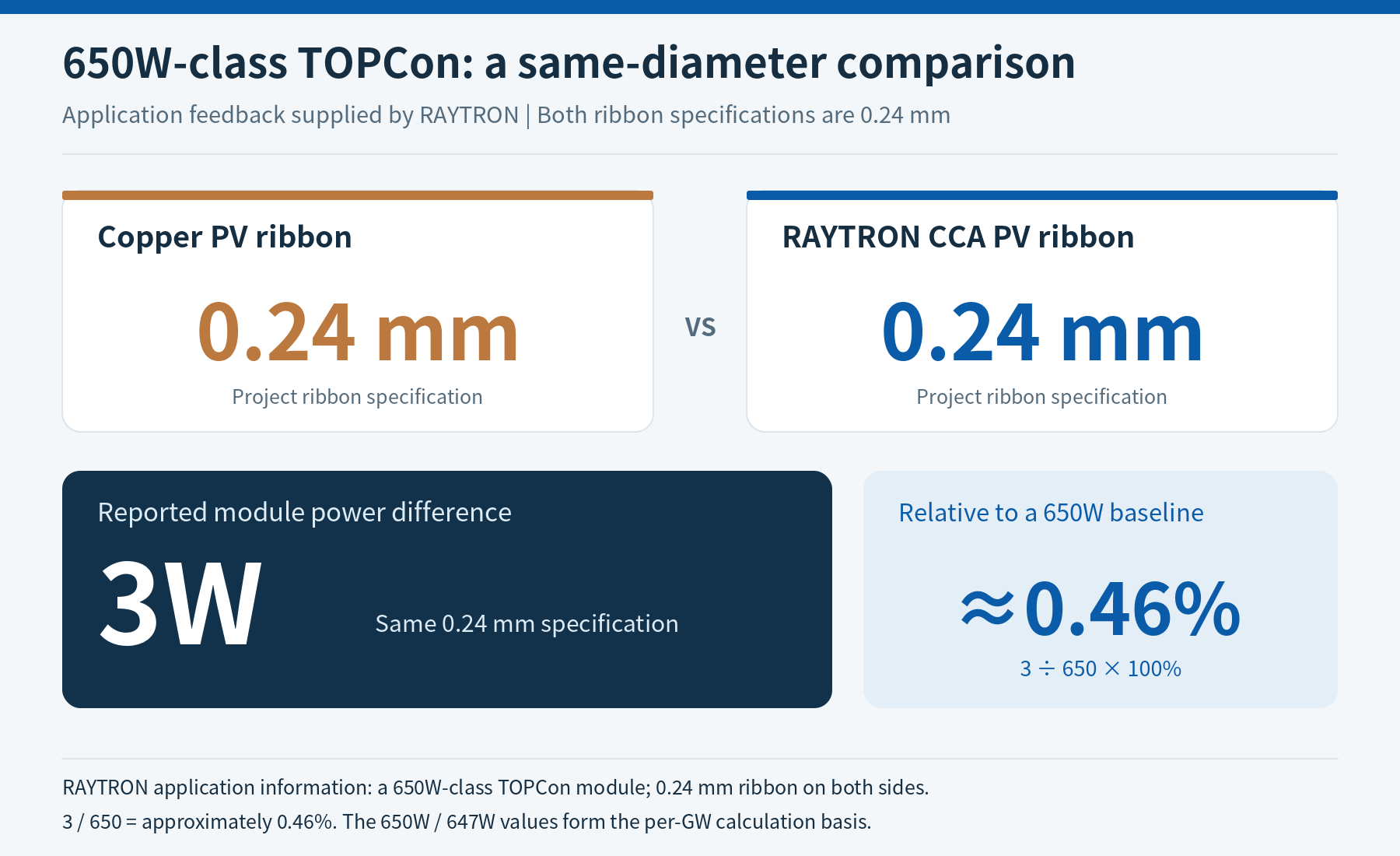
This application gives manufacturers a useful reference for module output with the same specified ribbon size.
| Item | Copper design | RAYTRON CCA design |
|---|---|---|
| Cell technology | TOPCon | TOPCon |
| Ribbon specification | 0.24 mm | 0.24 mm |
| Application power result | Reference | 3W below the reference |
| Normalized to a 650W baseline | 650W | 647W |
| Relative power difference | — | Approximately 0.46% |
650W/647W is the calculation basis used to illustrate the 3W difference and the purchasing model below. The supplied application information is a 650W-class module, 0.24 mm ribbon on both sides and a 3W difference.
Why can module output remain close when the metals have different conductivity?
Ribbon resistance per metre is a material property; module power is the output of the complete cell and interconnection system. The actual current paths connect the two.
For a conductor segment, resistive loss follows P_loss = I²R. Current passes through cell collection paths, intercell bridges and string connections. Conductor dimensions, wire count, path length and joint resistance together determine interconnection losses. Wire geometry and the encapsulated optical path also affect output. Fraunhofer ISE approaches interconnection development through electrical, optical and thermomechanical performance together.1
RAYTRON therefore organizes selection around ribbon cost per module, module power and sustained production performance. The 0.24 mm application supplies a practical starting point; other layouts are selected using their own module comparisons.
2. Translate ribbon savings from each module to each GW
Per module: convert the finished-product quotation into actual ribbon expenditure
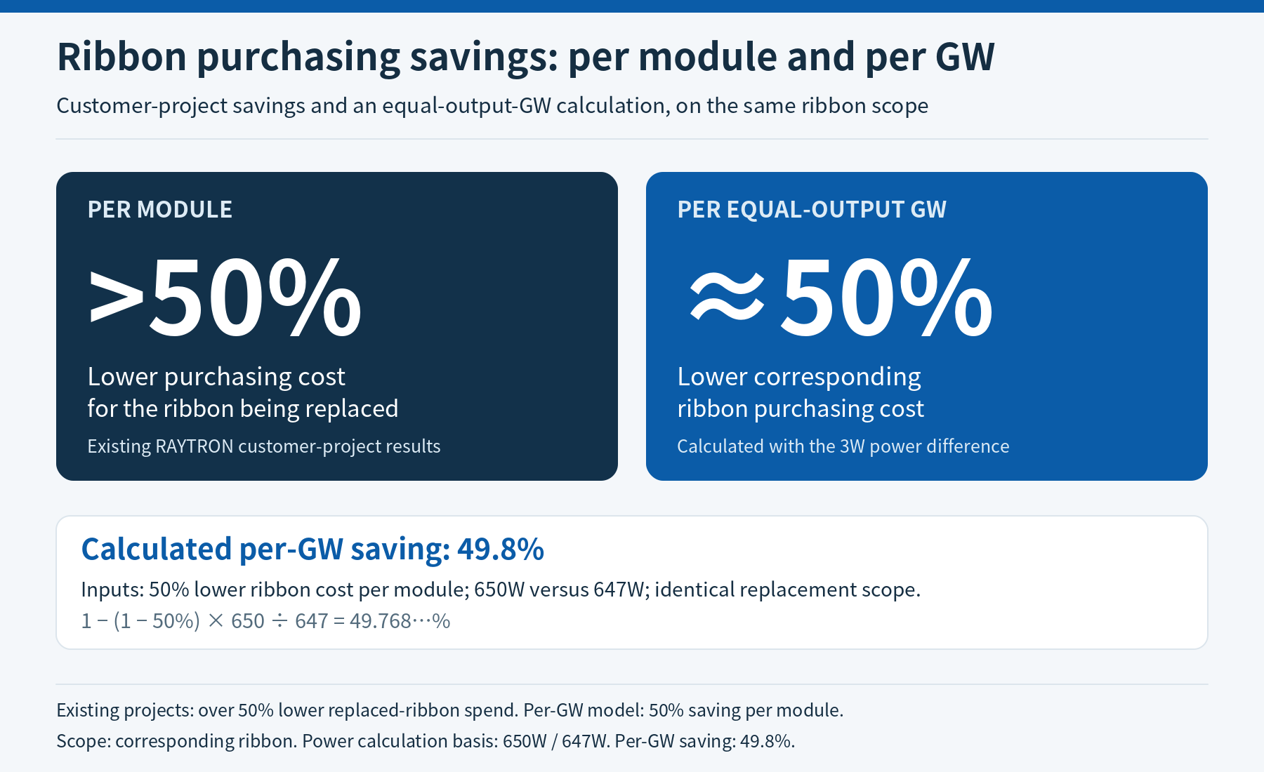
More than 50% lower purchasing cost for replaced ribbon in existing projects is the direct procurement value of RAYTRON CCA ribbon. Calculate interconnect ribbon and busbar ribbon separately, then total the categories included in the replacement.
Ribbon price per metre = finished-product price/kg × finished mass per metre (kg/m)
Ribbon purchasing cost per module = Σ(price per metre × corresponding purchased length)
Per-module ribbon saving = 1 − CCA ribbon cost / copper ribbon cost
Use consistent tax, freight and delivery terms. A finished-product quotation that includes solder coating enters the calculation directly. Apply the same treatment of production losses to purchased length so the comparison connects to actual consumption.
Price/kg alone misses the effect of mass per unit length. Put cost/metre, cost/module and cost/GW on the same purchasing sheet.
Per GW: account for the 3W difference and retain approximately 50% ribbon savings
Use a 50% reduction in replaced-ribbon cost per module as the budget input and 650W/647W as the power basis. For equal 1GW module output capacity, the calculation includes the additional modules required by the CCA design:
Ribbon saving per GW = 1 − (1 − per-module ribbon saving) × copper power / CCA power
                     = 1 − 0.50 × 650 / 647
                     = 49.768…% ≈ 49.8%
| Purchasing comparison | Copper design | CCA design |
|---|---|---|
| Replaced-ribbon cost index per module | 100 | 50 |
| Power calculation basis per module | 650W | 647W |
| Modules corresponding to 1GW | Approximately 1.5385 million | Approximately 1.5456 million |
| Ribbon purchasing cost index per GW | 100 | 50.23 |
| Ribbon purchasing reduction per GW | — | 49.8%, approximately 50% |
This answers a specific purchasing question: after adjusting module quantities for the power difference, how much ribbon expenditure remains saved? Under these inputs, the answer is still approximately half.
This budget covers ribbon purchasing. Evaluate complete-module economics separately, including cells, glass, frames, processing and power-bin changes. Each calculation retains a clearly defined cost scope.
3. Aluminum core, copper cladding and solder: give each layer a clear job
RAYTRON CCA PV ribbon uses a copper–aluminum substrate for conduction and an outer solder coating for joining. The aluminum core lowers density and copper consumption, continuous cladding provides a copper surface, and the solder coating matches the joining process.
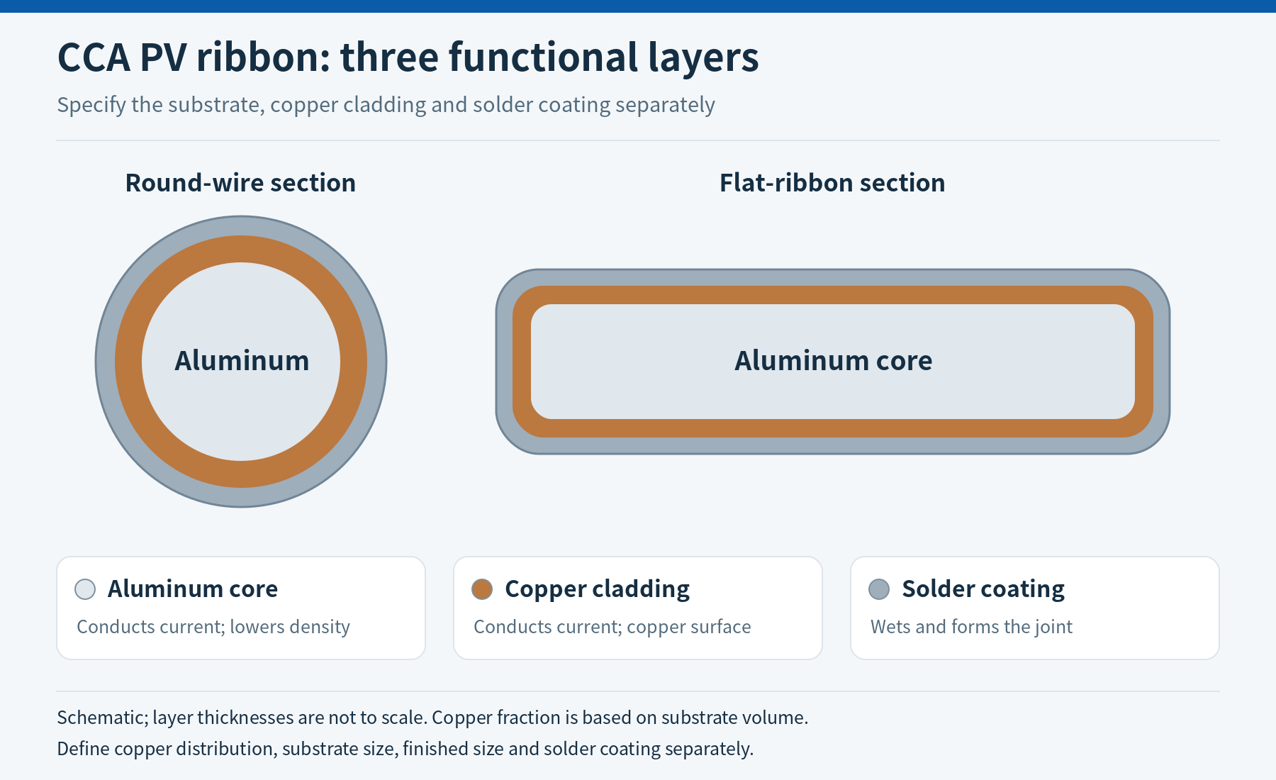
Schematic; layer thicknesses are not to scale. Copper content is defined by substrate volume, with solder composition and thickness specified separately.
| Layer | Function | Specification focus |
|---|---|---|
| Aluminum core | Provides most of the section, carries current with the copper and reduces substrate density | Core material, resistance, area and processing condition |
| Copper cladding | Carries current and provides a continuous copper surface | Copper volume fraction, circumferential/edge distribution, local minimum thickness and bond condition |
| Solder coating | Wets the mating surfaces and forms the joint | Alloy, thickness, uniformity and actual soldering profile |
For round wire, state substrate diameter and coated outside diameter. For flat ribbon, state width, thickness, corner geometry and surface requirements. Purchasing, stringer setup and incoming inspection then use the same dimensional definitions.
CCA ribbon value comes from layer ratio, dimensions, resistance and joining surface designed together. Copper content is a construction input; module output and line results guide the final choice.
4. What RAYTRON controls together
RAYTRON's material work spans copper–aluminum cladding, drawing, precision forming, annealing, surface treatment and winding. The objective for a module manufacturer is an agreed ribbon specification that fits production and provides consistent inputs for subsequent batches.
| Manufacturing control | Specific focus | Value for module production |
|---|---|---|
| Cladding and bond | Overall copper fraction, local thin regions, edge/circumferential distribution and integrity after forming | Maintains the defined copper surface at the joining location |
| Dimensions and resistance | Substrate/finished size, roundness or width/thickness, mΩ/m at a defined temperature | Connects each metre of ribbon to the module's electrical budget |
| Annealing and mechanical condition | Yield behavior, elongation, springback and formed condition | Matches feeding, intercell bends and cell loading |
| Solder and joining window | Alloy, coating thickness, wetting and actual heating profile | Matches cell metallization and stringing conditions |
| Winding and delivery | Spool, winding, tension, joint agreement and lot identity | Supports continuous payout, placement and repeat purchasing |
Review dimensions and resistance as a pair
Geometry explains why: a 2% reduction in round substrate diameter reduces area by 3.96% and increases resistance per metre by approximately 4.12%, at unchanged conductivity. Recording both makes fine-wire inspection useful for production, rather than treating them as unrelated pass/fail boxes.
Record where a joint fails to make process adjustment effective
Read peel force together with the fracture location: solder interface, metallization, conductor or cell. Each points to different material or process adjustments. Record wetting, joint resistance and the temperature profile alongside it to identify the part of the process that needs attention.1
The discussion with RAYTRON is about how a ribbon works consistently in your module—not only its price per kilogram.
5. Select for BC, TOPCon and busbar connection positions
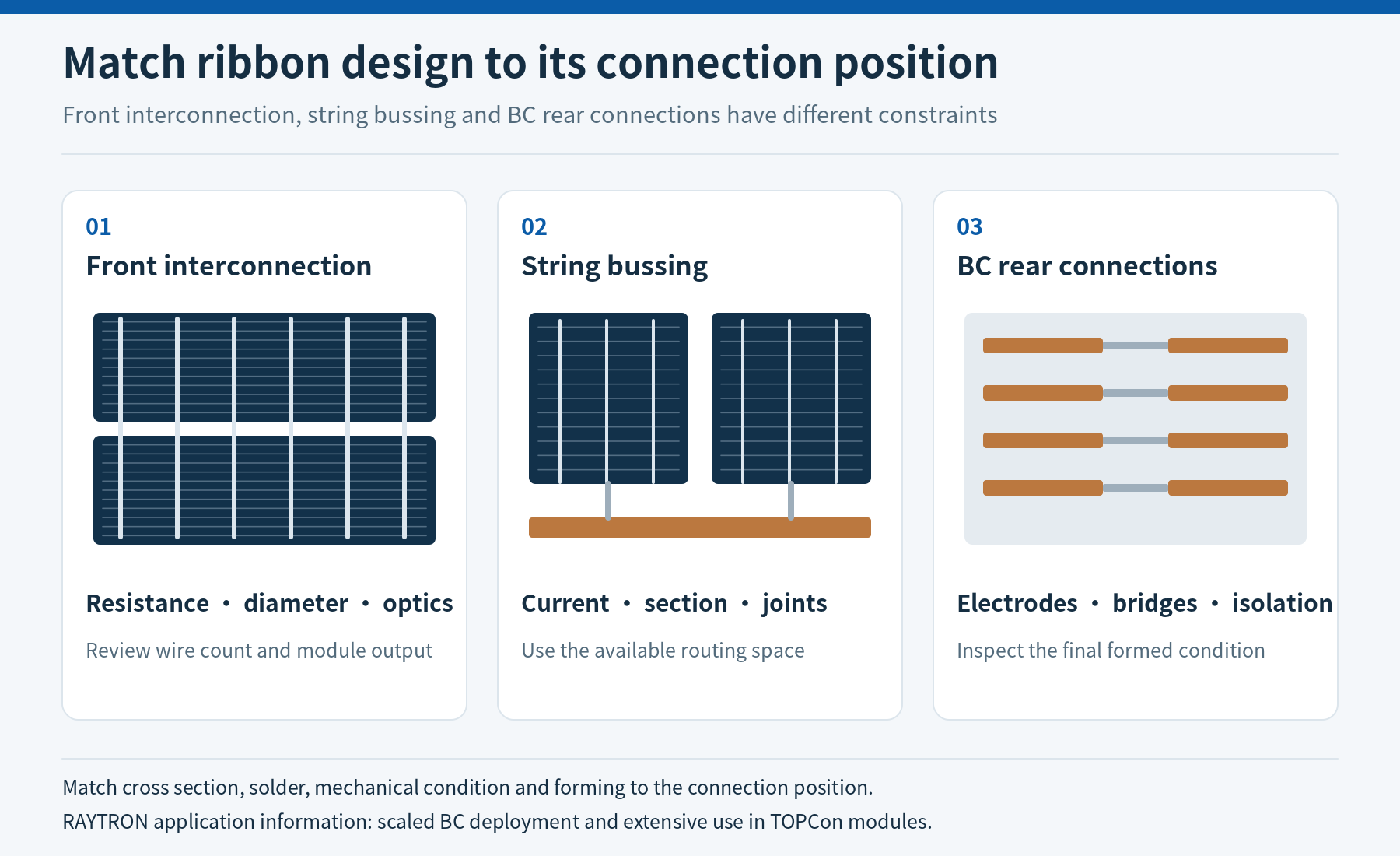
Connection-position schematic. Dimensions, conductor count and circuit details follow the module design.
BC: scaled application experience applied to the rear connection
RAYTRON CCA ribbon is already deployed at scale in Chinese BC modules. New projects start with the rear-electrode layout and define bridge geometry, polarity separation, local forming and joint condition. Check the cladding and solder at bent or flattened locations in their final formed condition.
That application experience moves the conversation directly to the customer's connection layout and production conditions.
TOPCon: extensive use and a concrete same-size reference
The 650W-class, 0.24 mm comparison with a 3W difference is a specific RAYTRON TOPCon application reference. For a new project, put wire count, spacing, length, coated dimensions and measured module power on the same comparison sheet, then add ribbon cost per module and continuous-production results.
Busbar ribbon: use the available width, thickness and routing space
Busbar ribbon connects cell strings and carries current toward the junction box. Select around actual current, length, available space, bends and end connections. Where width or thickness can be adjusted, design the section to the resistance target before comparing cost per metre.
Interconnect and busbar options can be introduced in stages, starting with the category whose consumption, cost and introduction conditions are clearest.
6. Start with one specification and three practical outputs
For the first discussion, send your current ribbon specification, or the cell technology and ribbon dimensions. Include quotation, consumption per module and stringer details already available; complete the other inputs during the discussion.
| Output to discuss with RAYTRON | Purchasing and engineering decision |
|---|---|
| Candidate CCA specification: dimensions, cladding, solder and mechanical condition | Which option enters sampling? |
| Per-module/per-GW purchasing comparison: finished mass per metre, consumption and comparable quotations | How much ribbon expenditure can be saved? |
| Line-trial priorities: stringing window, module output and production records | How will the material fit this module and line? |
Follow a defined sample-to-purchasing path:
| Stage | Principal records | Output |
|---|---|---|
| Material and stringing | Dimensions, resistance, solder, tension, heating profile and joint condition | A ribbon/process combination for the line |
| Module and continuous production | Power, EL, joint behavior, consumption, yield and downtime | Output difference and actual ribbon expenditure |
| BOM and repeat supply | Project reliability/change evaluation; confirmed specification and delivery requirements | An agreed basis for subsequent purchasing |
Module material-change retesting can follow the applicable IEC 61215 and IEC 61730 requirements and the IEC TS 62915 framework within the customer's existing quality system.2
Establish the saving per module, then use samples to align output and production performance.
Frequently asked questions
Is RAYTRON CCA ribbon already used in module production?
Yes. It is deployed at scale in Chinese BC modules and widely used in TOPCon modules. New projects build on that application experience and match the customer's dimensions, connection structure and stringing conditions.
How much ribbon purchasing cost can be saved?
Existing customer projects have reduced expenditure on the replaced ribbon per module by more than 50%. Compare your copper baseline and candidate CCA specification using finished mass per metre and actual consumption. List interconnect and busbar ribbon separately.
What is the power difference at the same 0.24 mm specification?
In the reported 650W-class TOPCon application, the RAYTRON CCA design was only 3W below the copper design, approximately 0.46% on a 650W basis. Use this reference to begin the comparison and establish your module's output through the corresponding trial.
Why are per-GW ribbon savings still approximately 50%?
At a 50% per-module ribbon saving and a 650W/647W power basis, ribbon expenditure for equal 1GW capacity is 49.8% lower after accounting for the different module quantities. Keep the replacement scope consistent throughout the purchasing comparison.
How should a trial be organized on the existing stringer?
Start with the present equipment and joining process. Provide the stringer model, solder/flux and current ribbon information, then align payout tension, placement, heating profile and joint condition. Trial records establish setting changes and tooling requirements.
Is complete technical documentation needed for the first inquiry?
Start with a specification, or cell technology and ribbon dimensions. Define the candidate ribbon, purchasing comparison and trial priorities with RAYTRON, then complete the required technical parameters.
Put your current ribbon on a more competitive purchasing sheet
Start from actual BC and TOPCon applications and discuss a RAYTRON CCA ribbon option for your module.
Compare my ribbon option with RAYTRON · Explore composite PV ribbon · View composite busbar ribbon
RAYTRON — Engineering Every Micron.
Data and technical sources
BC/TOPCon deployment, the 3W difference at 0.24 mm and existing-project ribbon cost savings: customer-application information supplied by RAYTRON. The 0.46%, per-GW 49.8% and geometric relationships are calculated from the stated inputs.
General interconnection and trial methods: Fraunhofer ISE Interconnection Technologies. Material-change retesting: IEC TS 62915:2023.