
Engineering application guide
Electronic Leads and Connector Strips
A lead or contact must survive its forming process and make the required electrical connection. Copper-clad steel (CCS) narrow foil, nickel-clad copper strip and silver-surface copper candidates need different layer, joining and contact checks.
Discuss the assembly requirementsOn this page
From supplied strip to a connection
- 1Strip or narrow foil
- 2Stamped / bent lead or contact
- 3Joined contact region
The supplied material is distinct from the finished connector. The part drawing determines which faces contact, bend or join and which cut edges are exposed.
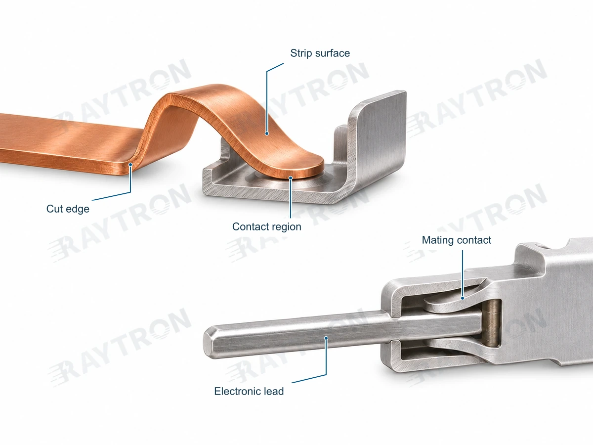
Copper strip, CCS narrow foil and NCC strip serve different material and surface requirements. Compare their layer construction, forming response and contact or weld behavior in the finished part.
Related conductor products
Design and testing
- Part and layer drawing
- Specify strip or foil width and thickness, layer sequence and ratio basis, temper, burr limits and exposed cut edges.
- Forming and joining
- Provide stamping and bending geometry, weld or solder method, terminal metals and required pull or shear acceptance.
- Contact and exposure tests
- Define contact force, current, resistance method, wear or cycling and environmental exposure. Evaluate the selected contact surface in the formed part and connection.
Application design factors
Lead and contact design starts with the conductor form, edge condition, surface metal and joining interface.
Application design record — open worksheet
Record your project requirements and observations, then download or include them in an inquiry.
| Item | Information / units | Your input |
|---|---|---|
| Part and surface | Drawing, mating metal/contact area, edge/burr direction, cladding or plating and exposed edges | |
| Process | Stamping/bending direction, tooling, coating continuity and actual joining method | |
| Record | Contact resistance or spring/load requirement, test method, lot/sample identity and deviations |
Other formats and preview
Save or restore a draft
Drafts stay in this browser. Clear inputs also removes the saved draft.
Worksheet version: RT-RFQ-WORKSHEET-1.
Which factors determine connector performance?
Contact geometry, force, surface condition, wear, cut edges and joining quality affect performance. Evaluate the formed component under its specified electrical and environmental duty.